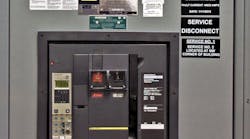

When OSHA performs an on-site inspection of a facility, it should be a nonevent, yet the trend these days is moving toward more citations, greater penalties, and more frequent inspections. Further complicating the matter is that local inspectors are not enforcing required codes for labeling, which is opening up clients to possible OSHA penalties.
The number of OSHA inspections performed in 2009 was about 39,000. This number grew to nearly 41,000 in 2011, and it is estimated there were more than 43,000 inspections performed in 2012. If you examine the total number of citations last year, you’ll see there were more than 82,000 handed out. The average fine issued for a serious violation in 2009 and 2010 was $1,000. In 2011, this number grew to $2,000. In addition, the number of willful violations continues to grow — from 401 in 2009 to 572 in 2011.
Compliance Safety and Health Officers (CSHOs) have been given instructions to get tough and are being given support from OSHA’s Solicitor’s Office, meaning companies can expect even greater enforcement of OSHA standards. Therefore, they need to be prepared for an inspection at any time. The reality is labeling, which is an important aspect of any inspection, often goes unnoticed until it is too late.
Labeling your facility is an important part of being OSHA compliant. Per OSHA 1910.335(b)(1), “Safety signs, safety symbols, or accident prevention tags shall be used where necessary to warn employees about electrical hazards, which may endanger them as required by 1910.145.” Because much of the equipment in most plants is interconnected, the use of proper labeling ensures safety and provides easier understanding of the system when it’s time for upgrades and repairs. Whether it is for the manufacturing of equipment or field marking, having everything properly labeled from beginning to end is not only important internally but also for those doing the actual inspections.
In this two-part series, some of the more important aspects of code-compliant labeling as it relates to the electrical infrastructure will be discussed. Part 1 focuses on service equipment, such as motor control centers, feeders, switchboards, and panels.
Let’s take a quick tour through a typical factory to determine some of the more important labeling considerations. First, power is coming in from the electric utility, which may come in on a cable tray or similar raceway. Per 230.44 of the 2011 NEC, the cable tray shall be marked with the wording: “Service-Entrance Conductors.” This service will enter the main service equipment, which needs to be marked with several key pieces of information.
 Ecmweb com Files Uploads 2013 05 305ecm Labe Lpic1" width="250" height="" />
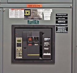
Photo 1. This image shows labels provided by the equipment manufacturer and those field marked by the installer. Note how the labels indicate system voltage and maximum fault current, as well as identify the equipment as a service disconnect. Per ANSI Z535.4, Art. 7.3 and Art. 8.1.2, informational labels like these can be made with white text on a black background or black text on a white background. Always follow the requirements of ANSI Z535 for designing your field-marked labels.
First, ensure that the maximum fault current is printed and displayed on your service disconnect. The fault current or amps interrupting capacity (AIC) rating denotes the maximum fault the breaker can interrupt without self destructing. The utility will look at the incoming potential on the primary, and then calculate what the potential is on the secondary side of its transformer. It will then publish a number that represents the maximum fault current the service should ever be able to see, and the breaker needs to be sized accordingly. Per NEC 110.24(A), this shall be field marked on the equipment (Photo 1). This particular label is not often seen on the required service equipment, because it is one of those regulations that is not commonly enforced. In addition, the service disconnect must also be labeled as the “Service Disconnect,” per NEC 230.70(B).
Per the NEC, you must also consider additional labeling if you have more than one service disconnect in your building. If so, you have to place an additional label that states the location of the other disconnect, as per NEC 230.72(A). This is critical for emergency personnel, should they need to shut down all power to the facility. Sometimes, a building requires a service that is so large the electric utility cannot supply the required power from a single set of lines. So you may end up with two individual utility feeds — usually with two separate meters.
For example, the facility might need both 120/240V and 277/480V power for larger motor loads. In some cases, these services may come in to the building at different locations. The mains for these different services must be marked to indicate where the other ones are located. A site plan of the building may show one service entering on the north side of the building and another coming in from the south. You would need to label the disconnects for these two unique services to indicate where the other one is located. If your service equipment is in a locked room or enclosure, you must also have a sign on the entrance that reads: “Danger – High Voltage – Keep Out” [see NEC 110.34(C)].
Moving on from the main service equipment, let’s examine the motor control center (MCC) or main distribution panel (MDP) as well as other vertical sections that contain the circuit conductors between the service equipment or the generator switchboard of an isolated plant and the final branch circuit overcurrent device.
Orange voltage markers still need to be applied to this equipment, which is normally done. However, a common mistake is to forget about labeling and identifying the breaker series rating of the MCC, MDP, switchboard, or panel. Per NEC 110.22(B) and (C), control panel enclosures of series-rated overcurrent devices are to be legibly marked to indicate the series combination rating. In NEC 110.24(A), the Code requires you to calculate the available fault current at the main disconnect (giving the required AIC rating). Yet, most electricians and inspectors don’t know how to do the calculations.
NEC 110.22(C) deals with equipment enclosures for circuit breakers or fuses applied in compliance with the series combination ratings, which shall be field marked. Typical ratings are 10k, 14k, 18k, 20k, 22k, 25k, 35k, 50k, 65k, 100k, 125k, 200k, and 300k. This has nothing to do with the amperage of the breakers installed in the panel. Instead, it relates to the AIC rating. Series rating and AIC rating are the maximum ampacity that the breaker can handle.
The smaller number printed on the breaker by the manufacturer is the minimum ampacity the breaker will handle before it starts to trip. This label is designed to show the series rated amps for that panel and specifies that those breakers or switches must be replaced by equally sized components. Many times, to save money, a company may replace a 65kA breaker with an 18kA breaker, which reduces the combination rating of that panel to 18kA. Doing this could be a hazard and result in an OSHA violation.
In addition, almost everything — from an industrial control panel to a switchboard or breaker panel and even the MCC — must have an arc flash label as defined in NEC 110.16 and NFPA 70E. This is also field marked based on fault calculations and such things as the minimum arc rating of the clothing, required level of personal protection equipment (PPE), the available incident energy and the corresponding working distance, highest hazard risk category (HRC) for the equipment, nominal system voltage, and the arc flash boundary. This all ties back into the series combination labels and maximum fault current ratings just described.
As with almost any panel, there are considerations for all equipment likely to require examination, adjustment, servicing, or maintenance while energized. Per NEC 110.34, equipment shall have clear working space in the direction of access to live parts, and that distance will vary, depending on calculations found in the NEC standard. A label shall be applied stating the minimum distance required on the front of the panel.
 Ecmweb com Files Uploads 2013 05 305ecm Labe Lpic2 0" width="250" height="" />
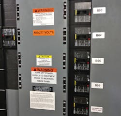
Photo 2. This switchboard is marked with an arc flash label, voltage indicator, and an isolating equipment label. Note that the phases on every circuit are marked, and a separate label identifies each circuit and its intended purpose.
Continuing per NEC 408.4(A), every circuit and circuit identification shall be legibly identified as to its clear, evident, and specific purpose of use. Most company personnel have typically thought to label and identify the circuits, but many forget other required signs that are critical to passing an OSHA inspection. For instance, before working inside an energized control panel, panelboard, or switchboard, you must post a warning label per NEC 225.70(2) advising against operation while carrying current (Photo 2), unless equipment is interlocked so that it cannot be operated under load. In some cases, the person servicing the equipment needs to understand that this equipment must be powered down before working on anything inside of it. Most panels and switchboards do not have an interlock that automatically cuts power when the panel is opened.
Information about the wiring in the panel is also important. A related requirement is NEC 210.5(C)(3), which defines the labeling of conductors originating within each branch circuit panelboard or similar branch circuit distribution equipment. The wires need to either be color coded or marked with color-coded labels.
Example: A = black, B = red, and C = blue (neutral is white)
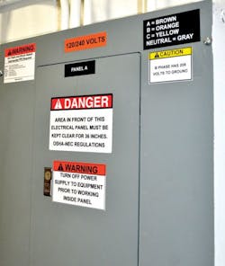
High voltage: A = brown, B = orange, and C = yellow (neutral is gray).
In addition, per NEC 408.3(E) and 409.102(B), these shall be documented in a manner that is readily available or shall be permanently posted at each branch circuit panelboard or similar branch circuit distribution equipment. The phases shall be permanently marked on the outside of the panel as “A, B, and C” from front to back, top to bottom, or left to right, as viewed from in front of the switchboard or panelboard. A simple label attached to the front of the panel is all that is required.
The 120V system is usually wired in black, red, and blue while the 277V version is wired in brown, orange, and yellow. While a 120V system is usually wired in black, if you have a 120/240V delta with a high leg, then the phases end up being in black, orange, or blue. The black and blue are industry standards not required by code. But any time you have a delta with a high leg, the high leg must be orange (per Code requirements). So, in theory, you could identify a 120/240V delta in brown, orange, or yellow, but it is not common.
 Ecmweb com Files Uploads 2013 05 305ecm Labe Lpic3" width="250" height="" />
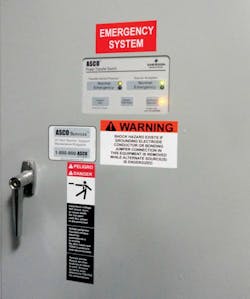
Photo 3. This transfer switch shows examples of how both labels are implemented in an end-user application.
It is important to label the phase-to-ground voltage because choosing the wrong value can result in damage to critical industrial automation equipment. One example is found in a 240V high leg system. If a contractor was to wire a connection from A phase to B phase, B phase to C phase, or A phase to C phase, the result is always 240V. However, if he changed the A phase or C phase to neutral, the result is 120V. Additionally, if the B phase is taken to neutral, the result is 208V. If an electrician is wiring something and assumes he is getting 120V and then actually receives 208V, the result could be equipment damage. In this particular instance, the B leg is required to be marked as a high leg and be colored orange.
As described previously, there is a NEC rule that states a 480/277V system is colored brown, orange, and yellow with the neutral gray. In a 120/208V system, the colors are black, red, and blue with neutral white. To make things more confusing, a single-phase 120/240V system is also black and red with the neutral white. This means it is possible to have a 3-phase system that, if not properly marked, resembles a single-phase system. In this case, if the A phase is taken to ground, the result is 240V. If the C phase is taken to ground, the result is 240V. However, taking the B phase to ground results in 0V, because it is intentionally grounded at the transformer — so there is no potential.
This is also why it is essential to label your high leg per NEC 408.3(F)(1), which states that a switchboard or panelboard containing a 4-wire delta-connected system, where the mid-point of one phase winding is grounded, shall be field marked to indicate which phase is going to ground and the associated voltage. Also remember to mark any circuits that are backfed. Each group-operated isolating switch or disconnecting means shall bear a notice to the effect that contacts on either side of the device might be energized per NEC 225.70(4).
 Ecmweb com Files Uploads 2013 05 305ecm Labe Lpic4" width="250" height="" />
Photo 4. This panel shows all the appropriate labeling as required by the NEC and NFPA 70E, per ANSI Z535 label design formats. Note how the phases are marked in this example.
Most facilities have a transfer switch that is designed to sense a loss of power and then transfer from the electric utility feed to an on-site generator feed to re-energize a panel or series of panels. Each transfer switch must be identified as an “Emergency System” in white letters on a red background per NEC 700.10(A), as shown in Photo 3. The NEC also requires a warning label, as per NEC 700.7(B) and NEC 701.7, that warns of a shock hazard if the grounding electrode conductor or bonding jumper connection in this type of equipment is removed while alternate energy sources are energized.
 Ecmweb com Files Uploads 2013 05 305ecm Labe Lpic5" width="250" height="" />
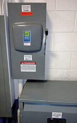
Photo 5. What's wrong with this picture? While the labeling is correct, there is a very blatant safety violation with the installation of the service disconnect feeding a separately derived system transformer in this case. The disconnect is located partially above the transformer. This installation violates Sec. 110.26 of the NEC. The depth of the transformer extends out past the front face of the disconnect, violating the clear space requirements in front of equipment that may need service while energized. Remember to always look to the codes and do not copy things that may be found pre-existing in the field.
Having the ability to prevent power loss to critical industrial automation and industrial control panels is essential to any business and important to the health and safety of those in charge of operating and maintaining such systems. The panelboards are considered branch circuits. As such, the path of power into and out of these panels is just as important as the main power, and vertical feeders and should be labeled and maintained to the highest standards possible (Photo 4).
Typically, the transfer switch is feeding into a transformer off a 480V line. NEC 450.14 indicates that transformers located in a remote location shall have a disconnecting means that is lockable, and the location shall be field marked on the transformer (Photo 5).
Having traceability from beginning to end is facilitated by proper labeling that is clear and concise and follows applicable codes. This article underscores the importance of proper labeling and how it affects the safety of everyone years down the road, when maintenance or repairs must be performed on equipment that is unmarked or improperly labeled with outdated information.
In Part 2, we will examine the labeling requirements of breakers and disconnects as well as the path out to industrial control panels and industrial automation equipment.
Fries is a technical consultant with HellermannTyton, North America, in Milwaukee. He can be reached at [email protected] .